Minimizing Fire Potential in Thermal-Oil Heat Transfer Systems
Thermal fluids have proven exceptionally safe in a wide range of industries. However, it is difficult to completely prevent fires in these systems because the necessary ingredients for a fire—fuel, air and ignition source—are present by design. The risk of fire can be minimized by observing sound design, installation and maintenance procedures.
Causes of Fires
Leaks – Small leaks around flanges, valve stems, etcetera are by and large more a problem of housekeeping than a safety issue. There will be some smoke and eventually a black stain. Small leaks can create a problem if the oil infiltrates porous insulation such as fiber glass and mineral wool. Such saturated insulation can catch fire when the cladding is removed.
Larger leaks caused by catastrophic failures of pump seals, rotary unions, flex hoses and expansion joints are more serious because of the large amount of vapor produced. And if the liquid falls onto a hot surface, sprays into an open electrical panel box or melts the plastic coating on high voltage wires, it can ignite.
Explosive Discharges may occur when the pressure-relief valve on the heater outlet lifts and dumps heated oil into an open topped, flat bottomed catch tank that has water laying on the bottom under a layer of oil. The water explodes into steam and atomizes the oil layer above it.
Sensor Failures – Pump coupling failures, malfunctioning by-pass valves and plugged Y-strainers can reduce or interrupt the oil flowrate through the heater. Safety circuits are incorporated to detect an increase in the outlet temperature, changes in pump or heater discharge pressure or a drop in the pressure differential across the heater or an orifice plate and shut down the energy source. But if the sensors have been by-passed or have not been maintained properly (failure of a thermocouple, plugged tubing) then the energy source may continue to heat the equipment potentially causing a rupture that releases superheated oil.
Cracked Heater Tube – Fired heaters are designed so that the flame never directly contacts the surface of the tube. Damaged or worn burners can cause flame impingement on the tubes which results in localized hot spots that can lead to coke formation. The coke insulates that portion of the tube resulting in uneven thermal expansion that in turn can cause cracks that leak oil into the combustion chamber. The oil then adds to the fuel value while the heater is running — but can pool when the heater is off and cause a major fire at start-up.
Heat Transfer Fluid & Hot-Oil Systems
The User’s Guide Series

- Analyzing Your Fluid
- Draining, Cleaning. Flushing and Charging
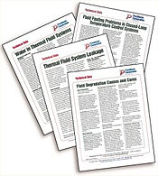
- Minimizing Fire Potential in Thermal-Oil Heat Transfer Systems
- Fouling in Heat Transfer Systems
- Water in Thermal Fluid Systems
- Oxidation in Heat Transfer Fluids
- Recommended High-Temp System Components and Suppliers
- Significance of Flash and Fire Points in Heat Transfer Fluids
- Fluid Degradation Causes and Cures
- Thermal Fluid System Leakage
- A Comparison: Thermal Fluid Vs. Steam
- How to Easily Track the Performance of Your Heat Transfer System
This sheet in bold
Design, Installation and Maintenance Tips
Heater Room Ventilation – Good ventilation will convert all vapors to smoke and cool the liquid portion to prevent further vaporization. Fresh air should enter low and exhaust high to provide maximum contact with any leaked oil. There should be air movement around critical areas such as pumps. If the heater room temperature is more than 25°F higher than the outside temperature, there may not be enough air flow.
Insulation – Foamed glass is the standard recommended material because it cannot absorb oil. Leaked oil will pool at the lowest point. Weep holes should drilled through the insulation to prevent excessive accumulation. Significantly lessexpensive to install than foamed glass, fiber glass and mineral wool can be safely used on horizontal pipe runs where the potential for a leak is negligible. All insulation should be covered with aluminum cladding to protect it from external leaks. Flanges should never be insulated. If personnel protection is required, install metal drip covers.
Piping – Expansion joints should be supported on both ends and installed so they move axially. Flanges should be used only around valves, pumps and equipment.
Pump Seals – Any vibration or noise should be investigated promptly. Seals should be replaced as soon as they start to leak. Do not install a plug in the seal chamber vent line. While a catch pan under a pump may sound like a good idea, if it’s not kept empty the oil will degrade from the heat and auto-ignite.
Pressure Sensor – The small diameter tubes that connect to the various pressure sensors are extremely susceptible to plugging if there are any carbon particles in the oil.
Catch/Overflow Tanks – The tank should be a closed head, dished bottom with a center mounted drain valve to allow complete draining and a high pressure sight glass. The vent should be directed out of the heater room to a safe area. If that is not possible, then it should be directed to a far corner of the heater room away from control panels, exit doors and combustion air inlets.
RELATED ITEMS
Fluid Degradation Causes and Cures Paratherm Web Article
Fluid Analysis: A Preventive Maintenance Tool Paratherm Web Article
