
Thermal fluid systems have been operating safely for many decades, across a wide range of industries. However, it is impossible to eliminate all risk in these systems as the necessary ingredients for fire – fuel, air and an ignition source – are all present by design.
While the established safety record of thermal fluid systems is a testament to proper system design and attentive maintenance practices, not all systems are designed and operated with best practices in mind. The evolution of remote sensing technologies and the Internet of Things (IoT) has helped to make thermal fluid systems even safer in modern times, but there remain several safety considerations for both new and existing systems that designers, engineers, original equipment manufacturers (OEMs) and operators should be aware of. Fire risk in thermal fluid systems can be minimised by understanding the causes of thermal fluid fires and mitigating those causes by observing key installation practices for design, installation, operation and maintenance of the systems.
Causes of fires in thermal fluid systems
Fluid and vapour leaks are the most obvious causes of fires in heat transfer systems. Small volume leaks around flanges, valve stems, etc., generally do not present any significant safety hazard. Leaked fluid usually oxidises, which creates smoke and eventually black stains. Nonetheless, small leaks can become hazardous if left unaddressed. No leak, small or large, should ever be ignored.
Catastrophic failure of mechanical components such as pump seals, rotary unions or expansion joints can quickly lead to dangerous conditions. High volume leaks create more ignitable vapour, and more material that can find an ignition source in the immediate surroundings.
Explosive discharges may occur from rapid pressurisation of the system. This scenario is commonly experienced when hot oil and water find each other. Rapid vaporisation of liquid water to steam may lift a pressure relief valve, and the steam may atomise oil as it exits. Catch tanks containing water have been known to create this scenario.
Component failures such as pump couplings, malfunctioning bypass valves and plugged Y-strainers can reduce or interrupt the oil flow rate through the heater. Safety circuits are standard for monitoring temperatures and pressures throughout the system. However, if safety interlocks are bypassed, or probes become fouled or unresponsive, a runaway situation can occur, creating conditions for superheated fluid and possible system rupture.
Cracks in heater tubes may form when damaged or worn burners cause flame impingement on the tubes, resulting in localised hot spots that can lead to coke formation. The coke acts as an insulative layer resulting in uneven thermal expansion and fractures that leak oil into the combustion chamber. The oil then adds to the fuel value while the heater is running, but can pool in the chamber when the heater is off, and cause a major fire at start-up.
Start smart: design and installation tips
Heat transfer systems should always be designed and/or reviewed by qualified engineers that are familiar with their construction and operation. There are several industrial standards that can be referenced for guidance in the construction of heat transfer systems. In addition to these standards and OEM recommendations, the next section of this article presents a few tips and best practices to improve the long-term safety and reliability of thermal fluid systems.
Putting it together
Piping networks should be designed for combustible fluid service – sized and installed to provide the required flow rate with an economical pressure drop. Standard construction material is schedule 40 seamless carbon steel pipe. All connections should be welded except where breakable connections are necessary, such as access/maintenance points around valves, pumps and equipment. Class 150 or 300 raised-face flanged connections are recommended, depending on the operating pressures/temperatures. To ensure proper gasket seating, raised-face flanges must have a proper surface finish.
Correct flange alignment is equally critical. Misalignment can result in overstressing one side of a flange while leaving the other without sufficient compression to seal the gasket. Once a flange pair is properly aligned, the lubricated fasteners must be incrementally tightened in a star pattern to maintain proper alignment and even compression. Applying adequate initial preload to the flanged connection will minimise the risk of leaks after system start-up. Once the system has started up, it is wise to ensure that flange bolts are checked for proper torque at normal operating temperature.
Flange gaskets are typically spiral-wound stainless or flexible graphite. Spiral-wound and grooved-metal gasket designs resist blowouts from sudden over-pressurisation, and are constructed for leak-free operation.
Threaded connections should always be avoided where possible. In lieu of threaded connections for instrument gauges/sensors, bendable tubing with compression fittings has been found to be a satisfactory alternative. Where threaded connections are necessary, the use of schedule 80 carbon steel is recommended, with pipe diameters not to exceed 1.5 in. (38 mm). Threaded connections should be joined using a thread sealant that is compatible with the thermal fluid and the operating conditions.
Expansion joints should be utilised to relieve stresses from thermal expansion of fixed structures (eg. circulation pumps). Such joints may include steel expansion loops, or ‘U’ bends, bellows-type expansion joints, or high temperature flexible metal hoses. Flexible expansion joints must be supported on both ends and installed in such a way that they move axially.
Valves tend to be a major source of leaks in thermal fluid systems. Leaks can be minimised by utilising valves with metal bellows (as the primary seal) in combination with high temperature graphite packing (as a secondary seal). In general, globe, gate, and rising-stem ball valves are the preferred choices for thermal fluid systems. Since valve stems are potential leak sources, they should be installed with the stem in a horizontal position if possible (provided that the valve manufacturer does not advise against this orientation). Should a leak occur in this configuration, the fluid will drip away from the valve rather than down into any insulation around the valve.
Keep the air moving
Where possible, heat transfer systems should be installed in open structures. For closed structures, explosion relief construction and adequate ventilation are critical safety considerations. High air exchange rates help to rapidly cool leaked vapour to smoke, and cool leaked liquid to prevent further vaporisation. The general rule of thumb is for fresh air to enter low and exhaust high, maximising contact with any leaking material. There should be air movement around critical areas such as pumps. If the heater room temperature is more than 25°F (13°C) higher than the outside temperature, there may not be enough air flow.
Prevent wicking potential of insulation
It is well understood that a combustible fluid can ignite at temperatures below its published autoignition temperature, if spread in a thin film. The high surface area present in many types of insulation can promote this phenomenon when soaked with a thermal fluid. Open cell insulation, such as mineral fibre, can wick, leaking heat transfer fluid into its porous structure. The wicked fluid proceeds to oxidise, which can raise the temperature of the insulation above the fluid’s autoignition temperature.
Foamed glass insulation is the standard recommended insulating material because it cannot absorb oil. Leaked oil will pool following the path of least resistance. Weep holes are sometimes drilled through the insulation to prevent excessive accumulation.
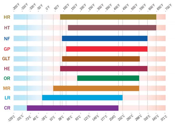
Figure 1. Fluid selection is critical to continuous performance, safety and reliability of the heat transfer system. It is important to specify a fluid that comfortably covers the entire operating range, including start-up conditions.
Mineral wool or fibreglass insulation can be safely used on horizontal pipe runs where the potential for a leak is negligible. It is wise to consider installing a metal drip ring to separate the fibrous material from the closed-cell insulation. It is also recommended that the insulation be covered with aluminium cladding to protect from external hazards, and that the use of insulating flanges is avoided wherever possible, as they are potential leak points. If fluid-soaked insulation is discovered, it should be addressed with haste and caution. Cladding and soaked insulation must be removed very carefully and slowly, preferably with the system cooled down.
Pumps and seals

Most high temperature systems utilise heavy-duty cast steel centrifugal process pumps with air or liquid-cooled stuffing boxes and bearings that are suitable for the process temperatures. Mechanical seals constructed of tungsten or silicon carbide are widely used. Mechanical seals should be installed with care, as fingerprints or dust/debris can create leaks. Some pump manufacturers may also specify a seal flush or inert gas purge to keep the seal faces free of debris and assist with secondary cooling. Despite best efforts, pump seals will eventually fail, and should be replaced as soon as they start to leak. A catch pan under a pump is not an acceptable fix, as accumulated oil can auto-ignite.
Seal-less pumps such as mag-drive or canned motor pumps eliminate many of the leakage issues associated with mechanical seals, and are often specified for systems operating above the atmospheric boiling point of the fluid. These pumps provide enhanced leak protection vs mechanical seals, but are more sensitive to accumulated degradation products and contaminants. Any vibration or noise at the pump should be investigated promptly. Expansion stresses on the pump should be alleviated by installing expansion loops, joints, or flexible piping rated for the process requirements.
Instrumentation and safety controls
Fire potential can be minimised by employing pressure, temperature, and flow monitoring controls throughout the fluid system, and at the process users. All specified components must be compatible with the fluid and the operating conditions, and failure scenarios should be considered during the selection process. Differential pressure gauges, flow control valves and temperature modulation should all be harmonised in such a way that the system responds uniformly to process demands.
Additionally, all safety controllers and components should be included in preventative maintenance schedules to ensure that they are working appropriately. Such controls may include over-temperature protection, low flow protection, expansion tank level alarms/interlocks, and relief devices that trigger when an abnormality occurs. In addition, continuous video surveillance at multiple points of the system can help to identify problems before they become catastrophic.
Catch/overflow tanks
These vessels are typically closed head and dished bottom with a centre-mounted drain valve to allow for complete draining, and are outfitted with a high-pressure sight glass. The tank vent should be routed out of the heater room to a safe area or adequate containment system. Catch tanks may also be outfitted with fire protection to minimise fire hazard at the discharge point.
Fire containment
In the rare and unfortunate scenario that a fire occurs, provisions must be available to contain and extinguish it as quickly as possible. Remotely-operated fail safes such as pump or fuel shut-off valves can go a long way in preventing a catastrophe. Automated sprinkler systems are recommended for release at critical areas throughout the system, such as at the heat source, in control rooms, and around relief discharges and process users.
Automated deluge protection may also be considered for critical areas. A system of containment dikes and reservoirs should be implemented to safely contain large volume losses. Class B fire extinguishers should be available in all critical areas for emergency response. Fireboxes may be outfitted with snuffing systems designed to prevent tube-rupture fires. These systems typically use steam or inert gas to snuff the combustion chamber in the event of a high exhaust stack temperature failure. Electrical equipment should be designed and installed to prevent ingress of heat transfer fluid.
Fluid considerations and proactive maintenance
The thermal fluid flash point is often the first thing that is scrutinised when determining the cause of a fire. In practice, nearly all high temperature heat transfer systems routinely and safely operate at temperatures above their fluid’s flash and fire points, but never above their autoignition temperature. The sequence of events that leads to most thermal fluid fires is nearly always a function of system failures and/or poor maintenance – independent of the fluid flash point. In practice, leaking fluid will cool quickly when exposed to air, dropping below the flash point. Any vapours produced will turn to smoke if the ventilation system is properly designed.
However, excessive heat flux can result in irreversible damage to the fluid, creating low boiling byproducts with lower flash points. These byproducts can reduce the operational safety margin of the fluid. As such, maintaining the health of the heat transfer fluid is also critical to the long-term safety and reliability of the system. In-service heat transfer fluid should be analysed at least once per year, and each time a process upset occurs.
For high temperature systems, testing should include a distillation range analysis to determine whether there are any accumulated low boilers. Excessive low boilers can cause mechanical problems (e.g. pump cavitation or unexpected pressure relief) and can generate higher vapour pressures if leaked from the system. Fluid oxidation level and solids accumulation should also be monitored, as these byproducts can also impact system safety. Accumulated sludges in the expansion tank have been known to interfere with proper functioning of the low-level switch, and sludges passing through the heater can further convert to coke, insulating heater tubes and creating hot spots, as previously discussed. Provisions for a side stream filtration loop are advised to keep solids accumulation at a minimum.
Conclusion
Relatively few fires have originated in thermal fluid systems since their adoption many decades ago. The majority of these have been caused by ignition of fluid-soaked insulation, loss of flow, cracked heater tubes, or leakage – all the result of improper design or operation and maintenance of the system. In general, all systems should be designed and/or reviewed by a qualified engineer who is familiar with the equipment.
By adhering to established design and installation guidelines, and by following all OEM recommendations and preventive maintenance schedules, the risk of a thermal fluid fire can be significantly reduced. All aspects of system design and fire prevention cannot be fully addressed within the context of this article. Designers and operators should always consult with knowledgeable experts and OEMs for the best recommendations.